|
|
|
|
SERVO SLOWERN.B. this is an old article describing Alan's prototype "servo slower" which has now evolved into a Servo Controller. You are strongly advised to visit that page rather than use this information!
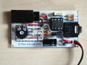
This unit is based on a 'PICAXE' micro-controller so all the clever stuff is done in software and as a result the parts count is minimal. The photo shows a prototype unit built on the readily available PICAXE project board AXE021 and the circuit diagram reflects that situation. Should you wish to build the unit on strip-board then the 3.5mm stereo jack socket (used to program the PIC over a serial link from your PC) can be omitted, together with the programming link LK1. If omitting the jack socket, R1 and R2 cannot be omitted - otherwise the serial input would 'float' and the PICAXE could interpret that as a signal from the PC (which it expects to be attached to this input) to enter re-programming mode. R1 and R2 can of course be replaced by a single 33K resistor. The white-ish looking LED is in fact a red/green bi-colour device which flickers at the transmitter frame rate to show the unit is operating. It flickers green whilst the servo is in alignment with the commanded position and flickers red whilst it is slewing to a new position. In the case of the 'straight through' mode being selected then the LED shows solid green. It also flashes red once per second if the input signal is not connected or disappears (eg a transmitter range problem) in either case returning the servo to its neutral position. The LED also gives a long red flash at each 'step' position as the slew rate adjustment pot is turned from end to end, so by counting the flashes it is easy to determine the 'slow' setting selected.
Circuit Diagram
Software After checking for presence of the input signal the program enters the main loop where it first monitors the setting of the slew rate adjustment pot, diverting to the 'straight through' mode if required. The input pulse width (ie commanded servo position) is then checked and compared with the actual servo position. If an error exists, then the servo is moved one 5 uSec step towards the required postion and the program drops into the main loop again. Thus after a number of steps at the transmitter's (nominal) 20mSec frame rate the servo finally reaches the commanded position and the output pulse-width is then repeatedly asserted to hold the servo in position. The slew rate adjustment pot sets the number of times to go round the 20mSec main loop before incrementing/decrementing the servo position and in this manner quite long duration traverses can be achieved. Each time round the main loop the input pulse-width is checked to lie within the permitted 1 to 2mSec range, and if a spurious pulse-width occurs then the previous good pulse-width is output, thereby giving some resistance to 'glitches'. But sustained out-of-range signal (or non at all) returns the program into the start-up mode, flashing the red LED once a second, waiting for resumption of a good signal. For safety, the servo is returned to neutral in this condition. Future plans are to implement a moving average filter to 'clean up' the input signal as a better method of eliminating any 'glitches'. My source code is not available - but on a local basis I am happy to 'burn' my program into your chip for any SRCMBC members. If you are further afield and really *must* make one, then contact me and we can probably come to some arrangement.
Variants Another idea is that a single blip of the stick causes a slow traverse to some defined position, hold for a period, activate a 'fire' signal and then return to neutral. A chip could also be programmed to continuously sweep a servo from side to mimic the movement of a forward facing radar scanner. Doubtless you will have other ideas, but the beauty of using a micro-controller is that such variants can be explored without needing to alter the hardware. So, let me have your ideas!
Parts List
* PL1 and SKT2 are created by cutting a normal servo extender lead in two. |


